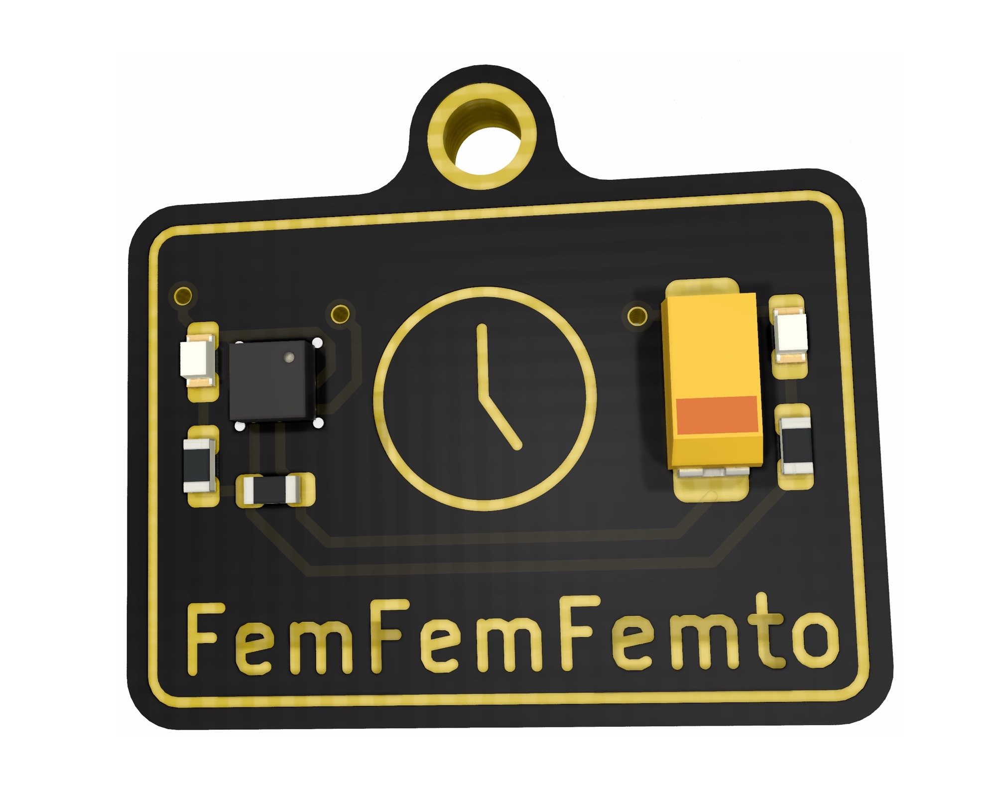
FemFemFemto
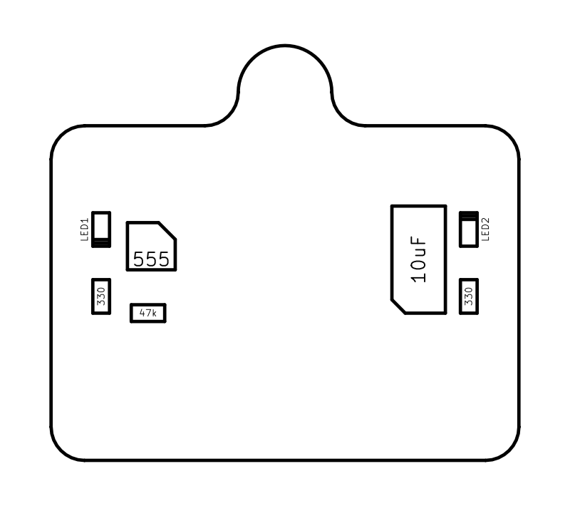
Component Map
Instructions
- Clean the PCB with isopropyl alcohol. (optional)
- Once dry, stick kapton tape over the gold outline, clock logo and FemFemFemto text. (optional)
- Put a tiny amount of solder paste on each of the pads for the LEDs, resistors and capacitor. Note: the 555 timer doesn’t require solder as it’s on the chip already.
- Place all the components onto their pads, making sure the LEDs, 555 timer and capacitor are orientated correctly.
- With a hot air gun on a slighly higher temperature than you normally use, but a very low air pressure, slowly bring it towards the PCB to melt the solder paste. Keep it a bit longer than you normaly would, to ensure the solder for the 555 timer has melted. 30 seconds or more is normal and ok.
- Leave to cool, then gently touch the 555 timer to ensure it has soldered…do this very very gently!!
- Stick kapton tape over the whole of the components side, then turn over the PCB.
- Get the battery holders, and press the springy contacts in a few times to make it easier to insert the battery later.
- It’s best to solder these with an iron, so add some solder to the 4 outer pads for the battery holder, but not the inner 2!
- Making sure the battery holders are turned the right way, put them on the PCB and then hold the soldering iron to melt the solder you added earlier. Add more solder if needed.
- Hopefully all has gone well, but it might take a few attempts to get this done. It’s not an easy kit to build, but so rewarding when it’s done.
- Add your batteries, and watch it blink!